Introduction to PWM into DC Fans
Have you ever pondered how the modern electronics around you remain cool, even under intense operations?
The secret lies in the precision and efficiency of Pulse Width Modulation (PWM) in DC fans.
This innovation has revolutionized the way our devices manage heat, ensuring optimum performance without the risk of overheating.
As you delve deeper into this topic, you’ll uncover the intricate details of PWM and its pivotal role in DC fan operations.
From its inception to its current widespread application, PWM’s ability to deliver precise control over fan speeds is truly remarkable.
This article will guide you through its intricacies, ensuring that by the end, you have a comprehensive understanding of its importance in the world of electronics cooling.
Basics of PWM
Definition of PWM in DC Fans
Pulse Width Modulation (PWM) for DC fans is a technique used to control the speed of the fan by varying the pulse width in a pulse train that controls the fan’s motor.
A PWM fan receives a constant voltage, but its speed is adjusted through the delivery of pulses of variable width. The width of these pulses determines how long the fan remains on high level (ON time) or Low level (OFF time), and this High-Low or ON-OFF pattern is rapid enough that it results in the modulation of the fan’s speed.
The Working Principle of PWM in DC Fans
PWM, is a method where a microprocessor’s digital signals govern analog circuits. To fully grasp the operation of PWM, it’s crucial to understand a fundamental concept known as the principle of area equivalence. The effect of narrow pulses with equal impulse but different shape on the link with inertia is basically at the same. In essence, when we consider two sets of inputs that differ in voltage and duration, provided that the total product of their voltage and time is equivalent, the resultant output waveforms will be fundamentally similar.
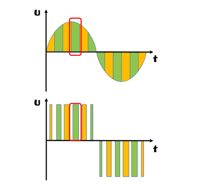
In Figure 1, you can see sine wave on top and square wave as below. The up-and-down color blocks in the alignment with the same color have equal areas, for exampled highlighted in the red frames. So standard sine wave depicted above the square wave showcased below are equivalent. This is why PWM can control analog circuits through digital outputs. It actually uses digital signals to achieve the effect of an analog signal. In Figure 1, a square wave pulse signal is used to implement a sine wave signal.
Related Concepts
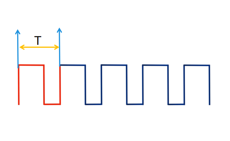
Cycle Time is the time which takes for a signal to go from the high level (ON time) to the low level (OFF time) and back to high level (ON time), shown as red color waveform (T) in the figure 2 as below. Unit: s or ms
PWM Frequency means how many of these cycles (T) are there in one second. Unit: HZ
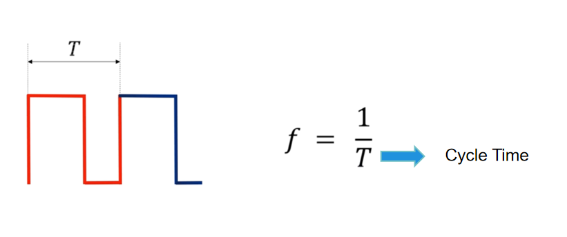
For examples, PWM frequency is 50HZ based on the cycle time of 0.02S. That means PWM signal varies between high level (ON time) and low level (OFF time) 50 times per second.
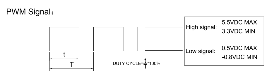
Now, we are coming to the most important concept, Duty Cycle, which is the ratio for the time PWM signal remains high level (ON time) against one cycle time, saying the percentage of the time PWM signal remains high level (ON time).
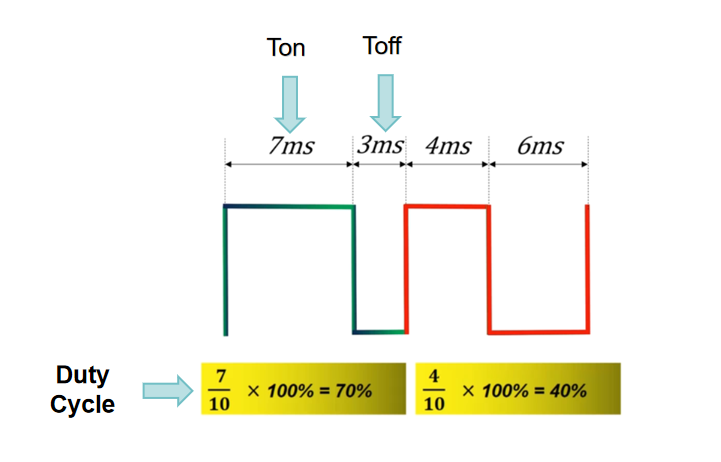
For examples, regarding 1st cycle in green color of figure 4 as above, PWM signal remains on high level (ON time) for 7ms and low level (OFF time) for 3ms. Hence:
Duty Cycle = Ton / (Ton + Toff) = 7ms / (7ms + 3ms) *100% = 70%
Here we introduce another concept, Pulse Width. It is the time PWM signal remains on high level (ON time) in one cycle. Hence,
Pulse Width = Ton = 7ms
Regarding the 2nd cycle in orange color, PWM signal remains on high level (ON time) for 4ms and low level (OFF time) for 6ms. Hence:
Duty Cycle = Ton / (Ton + Toff) = 4ms / (4ms + 6ms) *100% = 40%
Pulse Width = Ton = 4ms
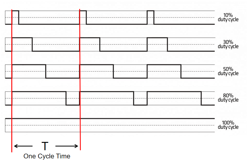
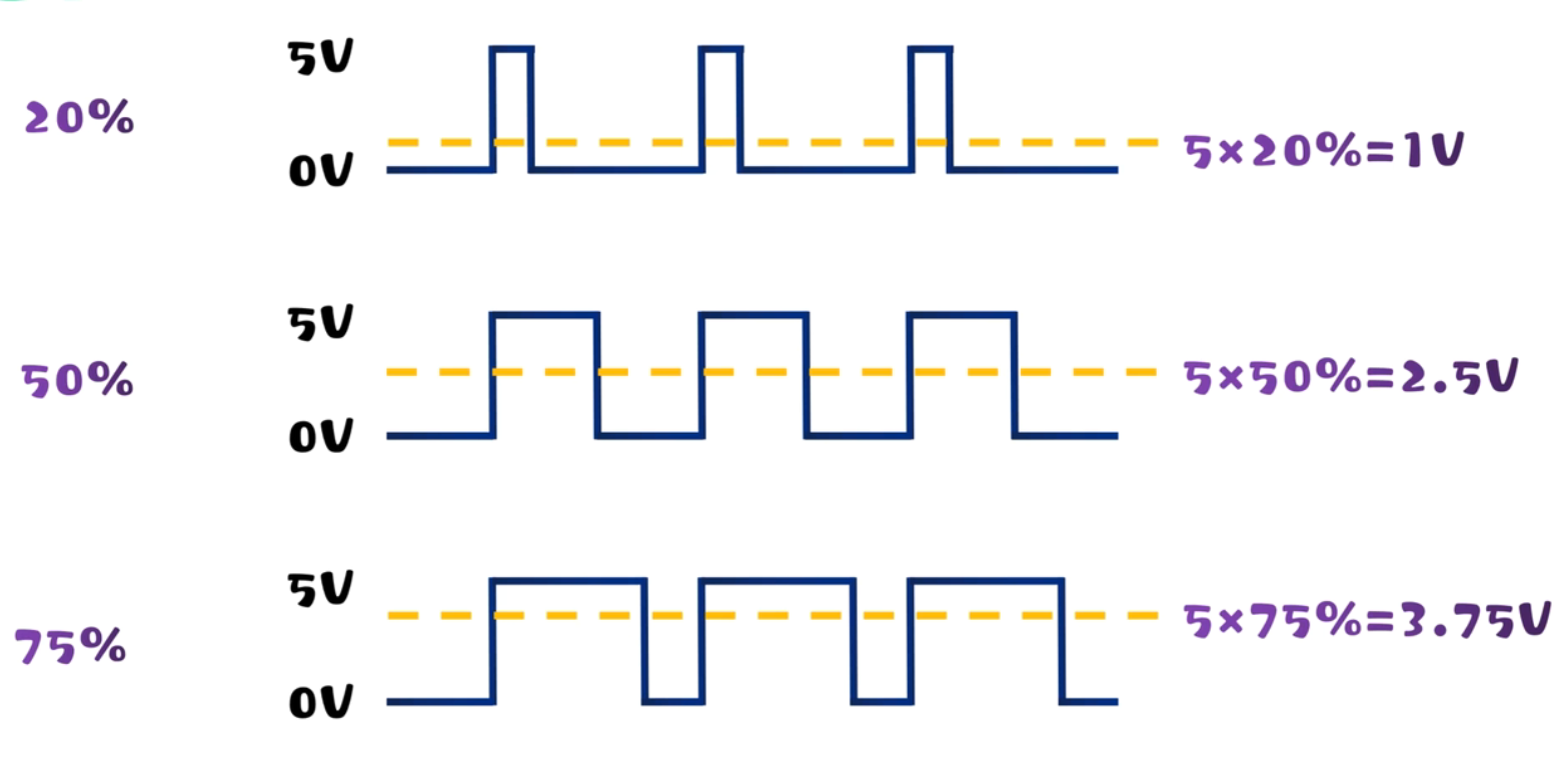
From Figure 5 & 6 as below, you can see different output waveforms from different duty cycles.
According to the area equivalence principle, the output is equal to the area multiplied by the duty cycle. From figure 7 as below, when PWM signal input is 5V and duty cycle is 20%, the average voltage is 1V (=5V * 20%); when duty cycle is 50%, the average voltage is 2.5V (=5V * 50%); when duty cycle is 75%, the average voltage is 3.75V (=5V * 75%). The higher of the duty cycle, the higher of the average voltage and the amplitude; The lower of the duty cycle, the lower of the average voltage and the amplitude.
By changing the duty cycles, we can get the sine wave we want as figure 8 as below.
CCHV PWM Operating Range
CCHV is a top DC fans & blowers manufacturer in China since 2006. We have experienced and professional in-house R&D team, which is mainly devided into mechanical group and electronics group.
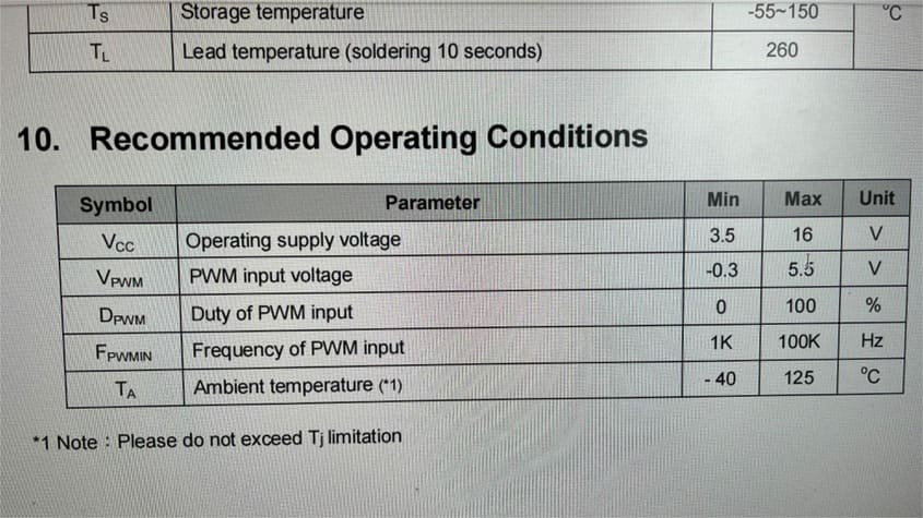
Here is our PWM Operating Range:
Note:
- Frequency range from the control board PWM signal is 18KHZ-25KHZ and preferred operating frequency to our fan is 25KHZ.
- Usually, when the fan works under 100% duty cycle, the fan will run at full speed. Can be customized.
- Usually, when PWM signal is disconnected, the fan will run at full speed. Can be customized.
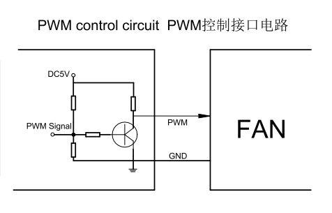
In each IC datasheet, PWM input voltage should be defined as below.
Even wondered: why we suggest to use 25KHZ PWM frenquency for DC fans? In DC fan industry, usually PWM frenquency is fixed from 1KHZ to 30KHZ, which can optimize the fan electromagnetic noise. Too low frequency will lead to poor motor operation and serious fan vibration; Too high frequency will lead to a large loss to the drive and even the motor screams without running. The appropriate PWM frequency range needs to be tested according to the motor power consumption.
Are you concerned about maintaining consistent fan performance across various duty cycles when switching to a new DC fan supplier? This case study will provide you with deeper insights.
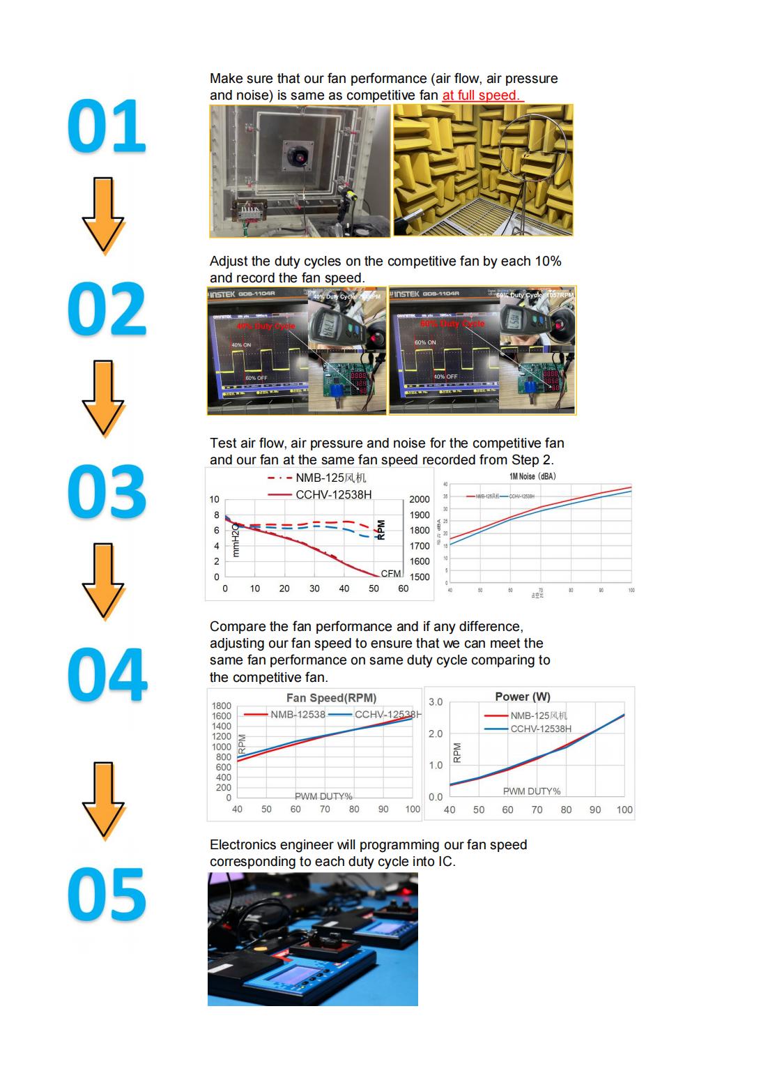
Please be aware that variations in impeller design elements such as spacing, number, angle, curvature, camber, and shape among different suppliers can lead to discrepancies in fan performance even at the same fan speeds. Consequently, to ensure consistent fan performance across all duty cycles in comparison to other competitive fans, it is essential not only to consider the fan speed but to prioritize overall fan performance. CONTACT US if you need further discussions.
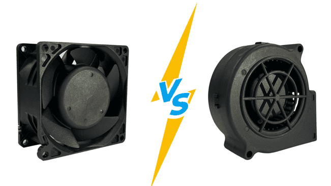
Hot Topic: 3-Wire DC Fan VS 4-Wire PWM Fan
Definition of 3-Wire DC Fan
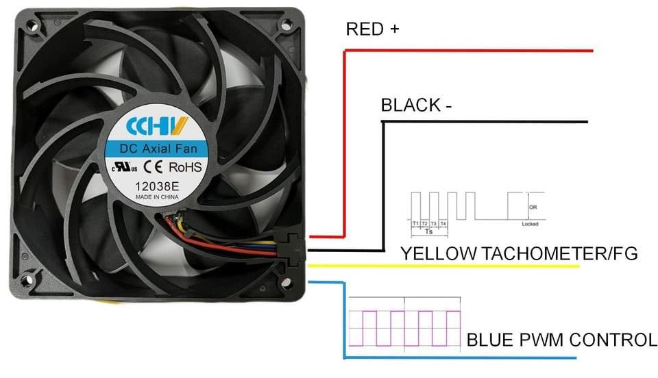
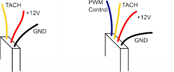
3-wire fan has power (red +), ground (black -), and tachometer (Yellow). The power and ground are for electrical supply, while the yellow wire, known as the tachometer or “tacho”, also called as FG/Frequency Generator, sends a signal to the microcontroller to report the fan’s speed.
Working Principle of Tachometer Signal in DC Fans
The working principle of DC fan speed detection operates on the Hall effect, utilizing a Hall effect sensor for implementation. These sensors can identify the existence and fluctuations of a magnetic field and translate these variations into electrical signals. Typically, the Hall sensor is mounted onto the fan’s PCB, where it can directly interact with the magnetic field produced by the spinning impellers of the fan.
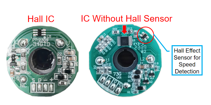
Fan speed monitoring can be achieved through two distinct circuit approaches: one that incorporates Hall ICs and another that necessitates an additional, separate Hall sensor. Hall ICs have an in-built Hall effect sensor, which provides a streamlined and space-efficient method for tracking fan velocity, making them particularly well-suited for compact spaces. These integrated circuits are optimally designed for low-power DC fans, typically those ranging between 2 to 5 watts in the consideration of heat dissipation issues.
Nevertheless, the intricate nature of Hall ICs programming will cause electromagnetic interference, which can diminish the precision of speed measurements. Therefore, for high-power DC fans, we usually adopt circuit scheme with external Hall sensor. Separate Hall sensors provide versatile positioning options on the printed circuit board, leading to designs that are less complex in terms of integration. This approach not only streamlines manufacturing but also improves thermal management, given that the sensor is not restricted to the compact confines of an IC package. Consequently, DC fans with higher power demands, especially those integrated into Brushless DC (BLDC) motors, benefit from the utilization of external Hall sensors, which facilitate superior heat dissipation.
Returnning to the topic how Hall Effect Sensor detects the fan speed: When the fan is running, the alternation of magnetic poles—namely the north and south poles—on its rotor induces fluctuations between high and low levels in the electrical signal. The swifter the rotor turns, the quicker these fluctuations occur. These shifts result in the generation of a square wave signal, whose frequency can be measured to ascertain the rotational velocity of the fan. To compute the actual speed of the fan, one would take the frequency of the square wave, multiply it by 60 seconds, and divide this product by the number of pairs of magnetic poles.
 |  |
Figure 14
The process of speed sensing in compact DC fans typically involves the emission of a square wave signal, with each complete turn of the rotor generating a specific count of square wave cycles. Although this count may vary across different fan models, it is common to see two cycles for each rotation. By precisely gauging the frequency of this square wave signal, the rotational velocity of the fan can be calculated.
Fan RPM= (Frenquecy ∗ 60) / 2
P.S.: In Figure 14, there are four poles on fan coil, therefore, one full rotation of fan represent 2 pulse signals.
How 3-wire DC fan controls the fan speed?
To adjust the velocity of the fan, you modulate the supplied voltage. By altering the direct current voltage delivered to the fan’s power line, its operational speed is correspondingly increased or decreased. The tachometer signal commonly emits two pulses for each complete rotation of the fan, furnishing an accurate method to gauge and control the fan’s pace. In managing the fan’s velocity, the control system or monitor measures the tachometer signal’s frequency, subsequently elevating or reducing the voltage directed to the fan based on the reading.
Definition of 4-Wire PWM Fan
Comparing to 3-wire DC fan, 4-wire DC fan gets 4th blue wire for PWM speed control.
Working Principle of PWM Speed Control in DC Fans
Kindly consult the previously mentioned details.
How 4-wire PWM fan controls the fan speed?
The PWM control wire is tasked with receiving varying pulse width signals from the device’s controller to regulate the rotational velocity of the fan’s motor. The fan’s PCB integrates an IC that deciphers the PWM signals and modulates the motor speed to match. This precise control mechanism facilitates granular adjustments of the fan’s velocity, enabling the creation of a finely tuned cooling environment essential for the thermal management of delicate electronic systems. Concurrently, the tachometer wire transmits a pulsed output reflecting the actual speed of the fan blades, which is instrumental for monitoring and maintaining desired operational speeds.
Benefit of using PWM control for DC Fans?
In the fast-evolving world of electronics, the demand for efficient and precise cooling solutions has never been higher. As manufacturers push the boundaries of performance, the need for advanced cooling techniques becomes undeniable. Enter PWM control for DC fans, a solution that stands out for a multiple reasons.
Precise Speed Control
One of the most significant advantages of PWM fans is their ability to precisely control the fan speed. Instead of running at a constant speed, PWM allows the fan to adjust its RPM (Revolutions Per Minute) in response to the temperature of the device it’s cooling. This dynamic adjustment ensures that devices are cooled effectively without wasting energy when full speed isn’t necessary.
More Energy Efficiency
PWM fans are generally more energy-efficient than their DC counterparts. By modulating the width of the electrical pulses sent to the motor, PWM fans can maintain the desired speed using less power. This not only saves energy but also reduces the operational costs over time.
Prolonged Fan Lifespan
Constantly running a fan at full speed can lead to shorten the fan lifespan. With PWM, since the fan adjusts its speed based on need, it can reduce unnecessary wear, prolonging the fan’s lifespan and ensuring that it runs quieter for longer.
Enhanced User Experiences
Nobody likes a noisy gadget. With the ability to run at lower speeds when full power isn’t required, PWM fans can significantly reduce noise levels, ensuring a quieter user experience. This is especially beneficial in environments where silence is golden, like offices or study rooms.
Conclusions
In conclusion, PWM (Pulse Width Modulation) fan control, incorporating tachometer feedback is essential for accurate thermal management. While PWM adjusts the fan speed by changing the duration of the electrical pulse supplied to the fan, the tachometer signal provides real-time data on the actual fan speed. This tach signal typically comes from a Hall-effect sensor and manifests as a series of pulses with each fan rotation, offering precise RPM (revolutions per minute) readings. By integrating PWM and tachometer feedback, we can achieve a good balance between cooling efficiency and noise for DC fans, dynamically adapting to cooling needs while maintaining energy savings.
FAQ
Q1: What is PWM fan control?
A1: PWM fan control is a technique that uses varying pulse widths in a high-frequency signal to regulate the speed of a fan without changing the voltage supplied to the fan motor.
Q2: Can PWM control be used for all types of fans?
A2: PWM control is typically used for 4-wire fans designed with PWM functionality in mind, as these fans have a separate wire for receiving the PWM signal.
Q3: What is the role of a tachometer in PWM fan control?
A3: The tachometer in a PWM fan control system provides real-time feedback on the actual speed (RPM) of the fan, which can be used to adjust the PWM signal for precise speed control.
Q4: How is fan speed measured with a tachometer?
A4: Fan speed is measured by the tachometer signal, which sends out pulses that correlate with the rotations of the fan impellers. The control system can measure the frequency of these pulses to calculate the RPM.
Q5: Can PWM control be used without a tachometer?
A5: Yes, PWM control can be used without a tachometer in circuit design, but you lose the ability to detect the actual fan speed.